Field Setup
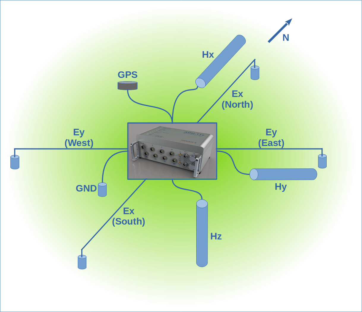
Location
The location of the MT station is the most important part of the field setup. The location should be chosen carefully to avoid noise sources. The following list gives an overview of the most important points to consider:
- Avoid power lines, power stations, transformers, and other electrical installations
- Avoid railways, highways; especially DC railways destroy the signal completely
The distance to the noise sources depend on the signal type and the surface resistivity.
- A harmonic signal is less harmful compared to a transient signal or rectangular signal
- In conductive areas the signal is attenuated faster than in resistive areas
So, simply spoken: a 50 Hz power line in a conductive, sedimentary area has a reasonable amplitude and does not destroy the spectrum.
A small village with a lot of power lines and transformers in a resistive area can destroy the spectrum completely over a distance of several kilometers (or water pumps in farming areas operating at night time … and so on).
Over all there is no other way but making a test measurement and check the spectrum. As a rule of thumb: after 15 min of recoding with a 512 Hz sampling rate you should get short but reasonable resistivity curve1. The amplitude in the H channels should be less than 4 V.
Orientation
Ideal is true North and East. You always want to align your data to the geographic North and East and with the geology and maps..
Hence that the EDI format may support different orientations, the MT software is designed to work with N-S and E-W orientation only.
So, if you rotate, and sometimes not … you leave an open door for errors.
An emergency solution is to rotate the time series data a.s.a.p. to N-S and E-W orientation. Store it, label it correctly, keep a backup.
Layouts differing from N-S and E-W are trouble makers
In case your +/- 25 m setup is blocked, make +10 m and -40 m for example. That is the better solution.
E-Field
The electric field is represents the most difficult part of the MT measurement!
Most of the noise intrudes by the electric field.
Check your electrodes.
Always orientate your setup N-S and E-W. This is the only way to compare your data with other data sets.
Additionally most of the MT software is designed to work with N-S and E-W orientation only.
Electrode Spacing
The electrode spacing depends on the frequency range you want to measure.
- 100 m (2 x 50 m) or more for LMT (long period MT), must use non-polarizable electrodes
- 25 m for AMT, steel rods are fine
- 5 - 10 m for frequencies above 25 kHz, must use buffered electrodes
- 50 - 25 m for MT, 8 hours recording time, steel rods can be fine, periods down to 1 or 10s
- 50 - 100 m for MT, more than 8 hours recording time, non-polarizable electrodes
For steel rods, test the contact resistivity before the measurement. They work only if the soil is moist. In case your use MFS-07e and make a broad and recording including some AMT, 50 m on each reel is fine.
In older versions you read that a greater spacings improves the data quality. So using 200 m spacing is better than 100 m spacing. This is still a valid assumption for low frequencies; however the pre-amplifier of the system is so good that you do not need to spend efforts in laying out a long E line.
In case you can only use 60 m spacing in total for LMT, use 60 m spacing.
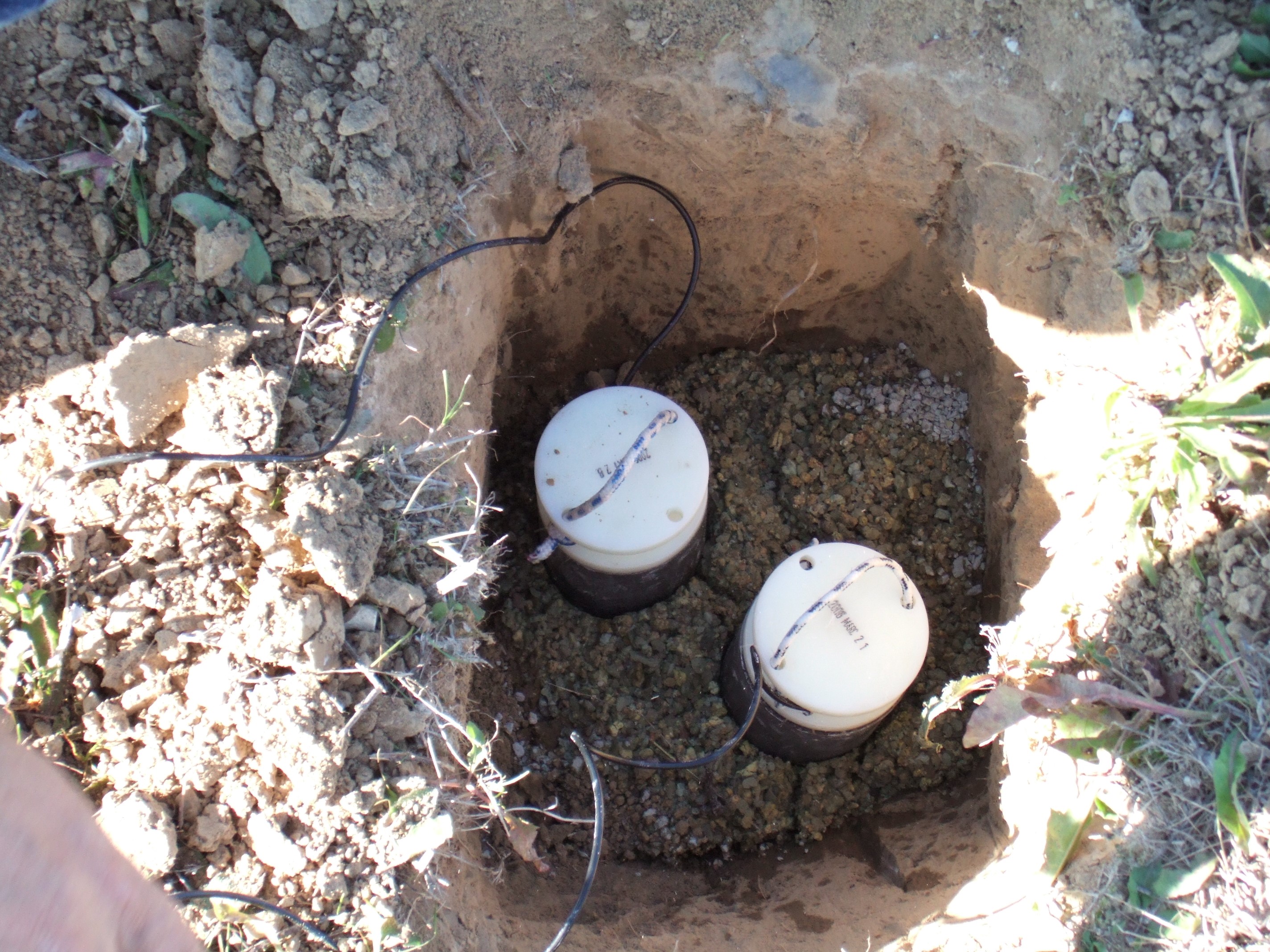
Electrode Depth
As deeper as better for LMT; if you reach the depth of natural moisture you are the winner.
In dry areas use an auger to dig a hole.
Understand: no good contact, no data!
Use bentonite to fill the hole and water it.
Never ever use salt!
Connect the cable to the cable drum:
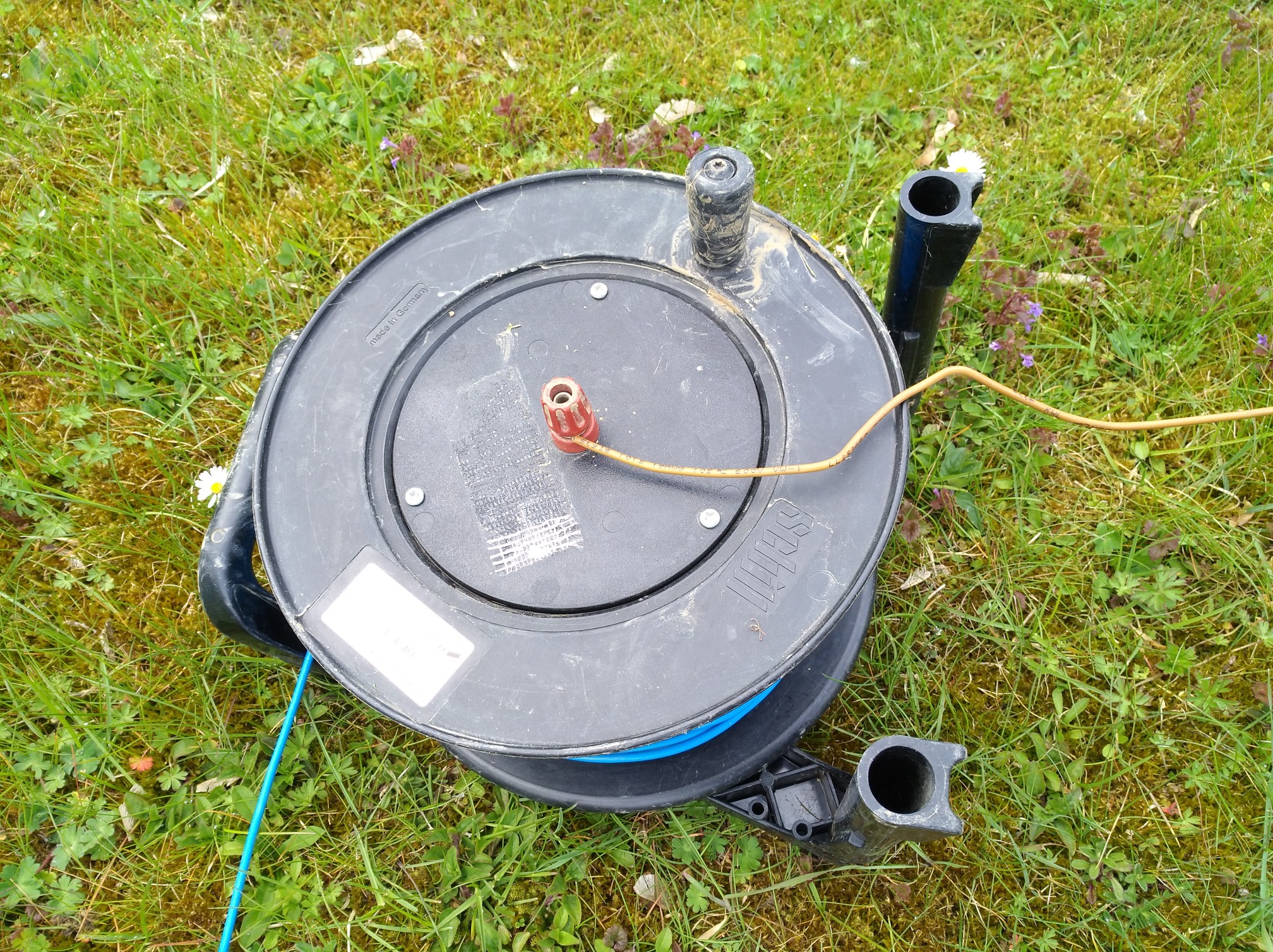
Turn upside down, that gives a tiny protection against water intrusion.
… and get data …
Until now I don’t understand why people spend a lot of money for undertaking a MT survey - but are not able to purchase an auger (or motor driller).
To improve the data quality, drill deeper:
Common Problems
- the electrode is not buried deep enough
- contact resistivity is above 4 k\(\Omega\)
- electrode falls dry
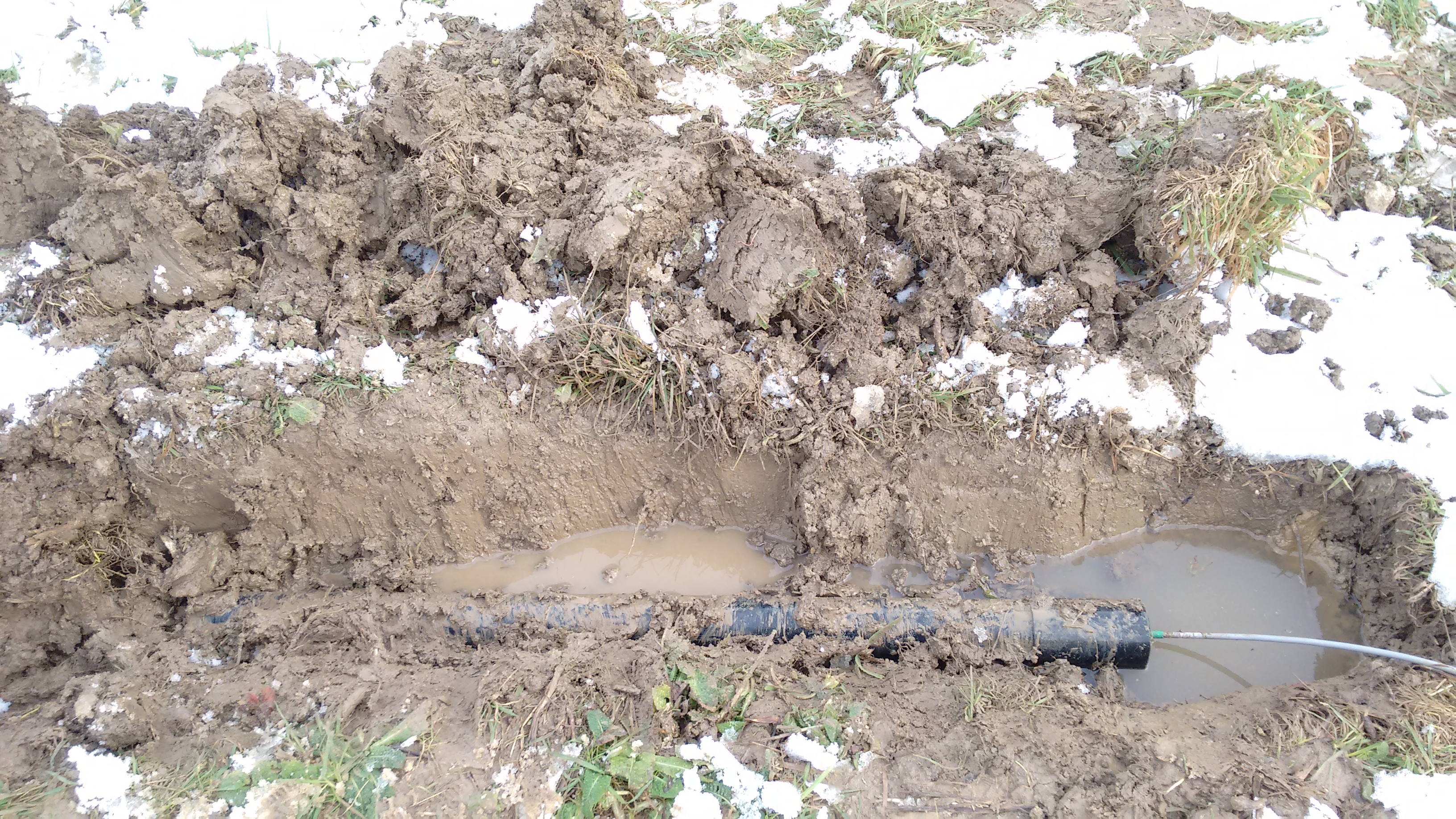
- cable is chopped by animals
Noise and Trash
Electrodes have their life time. Noise will increase, e.g. below 10 Hz. That is not easy to see in the data.
Follow the link here for EFP-06. Their lifetime is about 2 years (regardless of the usage time).
You can test the electrodes by measuring the self-potential.
H-Field
Use the full cable length to the sensor. The sensors will “see you” when changing the battery or when connecting the cable to your laptop.
20 m is the default cable length and you can use it for AMT and LMT.
Use the full cable length to the sensor.
Make sure that the coils is not directly placed beside the E line - keep 2 m distance.
Placement
20 - 40 cm deep for coils is fine. For a fluxgate, which has some temperature dependencies, go as deep as you can.
For the North coils the cable end is at South; for the East coil the cable end is at West.
- dig a trench
- level the bottom
- place the coil
- use the level again
- use a compass to orientate the coil (either N or E)
The coils are magnetic! Stand upright and orientate the coil to North or East, don’t lay the compass on the coil!.
Remote Reference Station
The basic idea of a remote reference station is to measure at the same time but not at the same place.
The distance between the stations should be estimated that way, that the noise sources are not the same, but the inducing magnetic fields are the same.
The electric field strongly depends on the local geology, and is mostly not used for RR; advanced processing techniques are needed.
In case you use RR for long periods, the distance should be 10, 20 km or more.
Local Reference Station
For AMT and LMT you can use a local reference station.
Especially for AMT in the dead band by simply using \(H * H_r\) (H against H reference of the next local station) you can improve the data quality; reason: the dominating problem here is often not external noise - but internal noise of the sensor. And exactly this is used here.
Combination
In case you don’t have many systems, try a combination from the above.
Laptop
WiFi
The ADU acts as a WiFi hotspot.
You will see system and serial like “ADU-10e 22”, and connect.
You need to authenticate with user and password when accessing the system.
In most cases this is the easiest way.
The WiFi switches off after 10 minutes of no activity.
Shortly press the power button to reactivate.
Your device may report “poor” or “limited” Internet access.
That is because the ADU does not connect you trough.
Some devices may disconnect and search for alternatives.
Auto connect while using the ADU may solves that problem.
Cable
Cat6 and above works for 50 m and more (20 m and above is needed to operate the ADU without any interference from you (your laptop / mobile phone))2.
You must set your IP address manually.
| system | IP | netmask |
|---|---|---|
| ADU | 192.168.40.10 | |
| Laptop | 192.168.40.2 | 255.255.255.0 |
| ADU | 192.168.20.10 | |
| Laptop | 192.168.20.2 | 255.255.255.0 |
As you can see, in case you have several generations of ADU (07e,08e,10e,11e,12e), you may configure multiple static addresses.
It is possible to configure the ADU IP address also.
If you have set your IP address identical to the ADU’s IP address you get no connection!